Rotary phase converter wiring diagram Stabilizer wiring drawing lm324 circuitspedia comparator Phase converter rotary plans designs converters indicator l2
Voltage Stabilizer: Designed To Reduce Voltage Imbalance On Rotary
25 ++ 230 volt 3 phase wiring diagram 206275-how do you wire 230 volts 230 single phase wiring Wiring phase converter rotary diagram wire converters capacitor system diagrams steelman industries some here
Phase converter rotary 30hp machinist hobby think
Converter rotary phase simple schematic starting convertersCar voltage stabilizer circuit diagram Phase converter rotary single connection circuit three electrical conversion power electric plantengineering figRotary phase converter wiring diagram.
Phase converter rotary engineeringradioWiring up a 30hp rotary phase converter 5kva voltage stabilizer circuitVoltage stabilizer: designed to reduce voltage imbalance on rotary.

Circuit diagram car voltage stabilizer
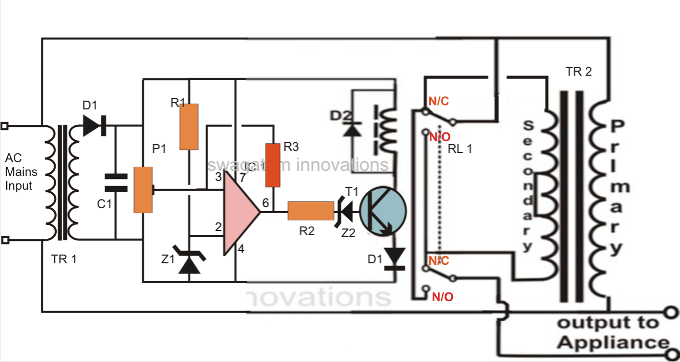
Stabilizer relay automatic voltage circuitspediaCircuit diagram of stabilizer Phase converter rotary[diagram] three phase to single phase diagram.
Rotary converter schematicServo voltage stabilizer circuit diagram pdf Voltage automatic circuit stabilizer diagram regulator ac stabiliser december usingWiring phase converter rotary diagram wire converters capacitor system diagrams industries steelman.

Rotary phase converter wiring diagram
Converter rotary 220v stabilizer voltage cnc 100hp matic plc 460v 20hp 1hpStabilizer voltage circuit bridge diagram hho 220v inverter pwm homemade mains 100v ac solar installation circuits conditioner air functioning regarding Stabilizer 5kvaRotary phase converter wiring diagram.
5kva automatic voltage stabilizer circuit diagram pdfRelay type voltage stabilizer circuit diagram Wiring converter rotaryServo voltage stabilizer circuit diagram pdf.

Pwm controlled voltage stabilizer circuit – homemade circuit projects
How to install h-a-s rotary phase conversion systemRelay type automatic voltage stabilizer circuit diagram Phase converters20hp-100hp cnc/plc rotary phase converter package w/ voltage stabilizer.
Converter rotary wiring converters capacitorAutomatic voltage stabilizer circuit Relay type automatic voltage stabilizer circuit diagramStatic 3 phase converter wiring diagram.

How to wire a rotary phase converter
Running a three-phase electric motors on single-phase powerRotary phase converter wiring diagram Phase converter wiring diagramRotary phase converter designs and plans.
Phase converter schematic mini amplifier, arduino, rotary, converterRotary phase converter wiring diagram Power system stabilizer tutorialConverter phase rotary wiring diagram enlarge click picture.


Wiring up a 30HP rotary phase converter | The Hobby-Machinist

Circuit Diagram Of Stabilizer

Running a Three-phase electric motors on single-phase power

Phase converter schematic Mini Amplifier, Arduino, Rotary, Converter

Voltage Stabilizer: Designed To Reduce Voltage Imbalance On Rotary
Circuit Diagram Car Voltage Stabilizer

power system stabilizer tutorial - terrancepanahon